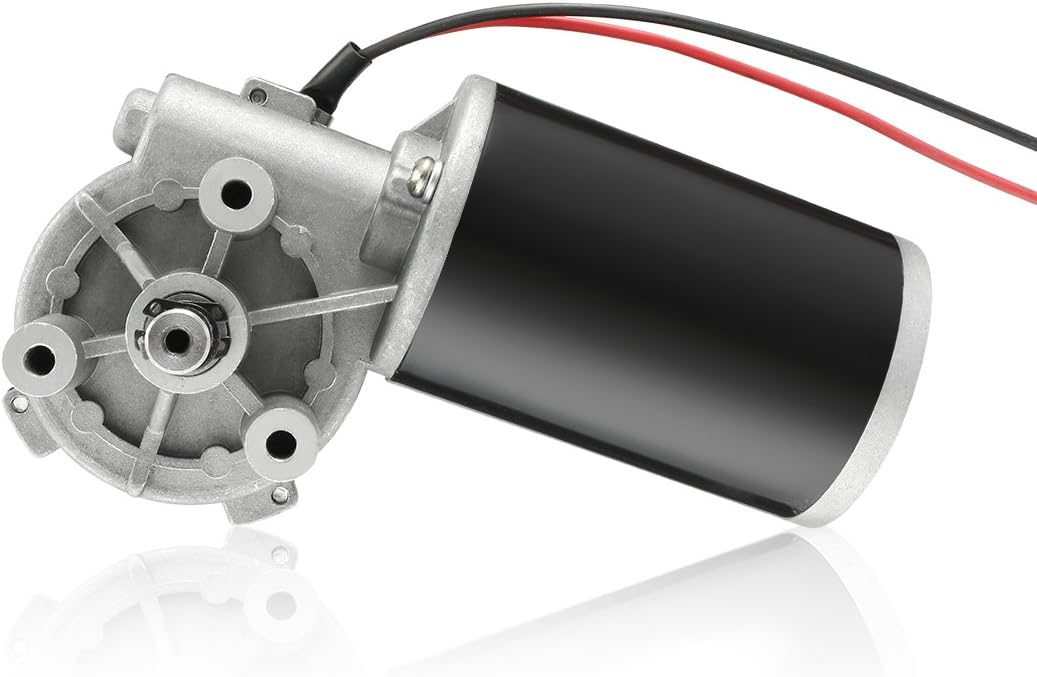
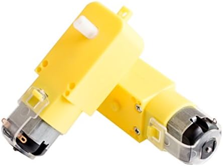
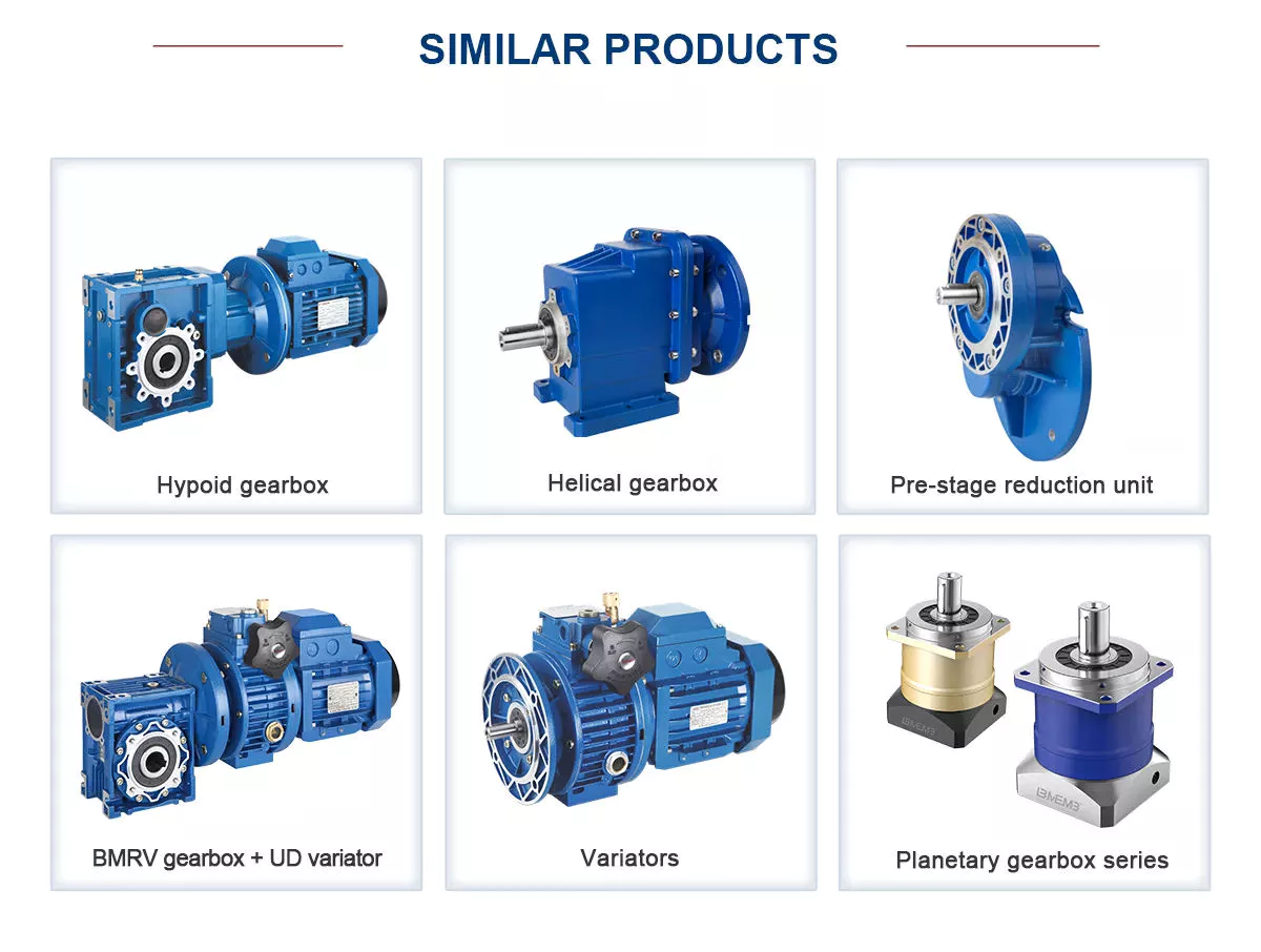
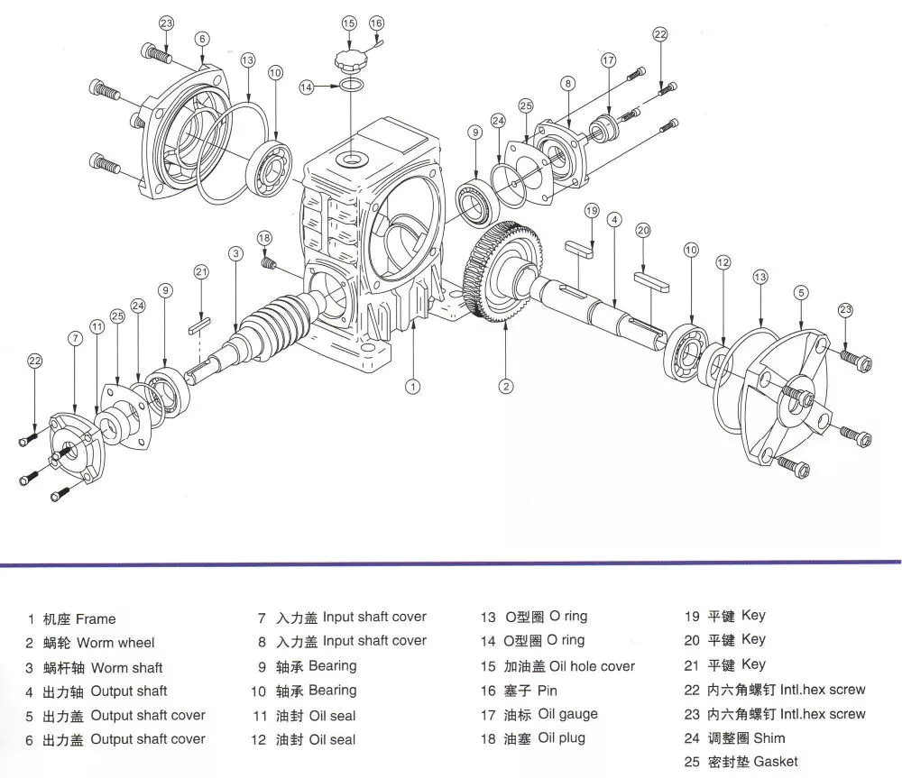
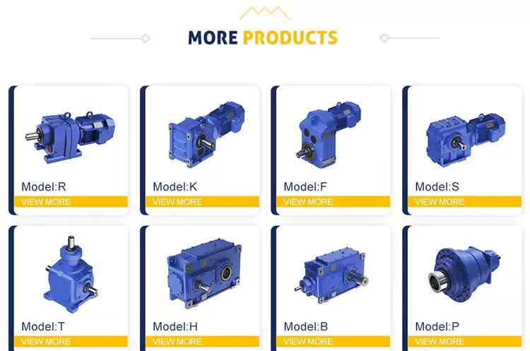
Product Description
NCJ series Helical Geared Motor
2:Technical parameters
| Model | Power rate(KW) | Ratio | Output torque(N.m) | Output speed(rpm) | |||||||||||||||||||||||||||||||||||||||||||||||||||||||||||||||||||||||||||||||||||||||||||||||||||||||||||||||||||||||||||||||||||||||||||||||||||||||||||||||||||||||||||||||||||||||||||||||||||||||||||||||||||||||||||||||||||||||||||||||||||||||||||||||||||||||||||||||||||||||||||||||||||||||||||||||||||||||||||||||||||||||||||||||||||||||||||||||||||||||||||||||||||||||||||||||||||||||||||||||||||||||||||||
| NCJ02 | 0.12-0.55 | 7.59-201.5 | 10.04-201.5 | 6.60-137.45 | |||||||||||||||||||||||||||||||||||||||||||||||||||||||||||||||||||||||||||||||||||||||||||||||||||||||||||||||||||||||||||||||||||||||||||||||||||||||||||||||||||||||||||||||||||||||||||||||||||||||||||||||||||||||||||||||||||||||||||||||||||||||||||||||||||||||||||||||||||||||||||||||||||||||||||||||||||||||||||||||||||||||||||||||||||||||||||||||||||||||||||||||||||||||||||||||||||||||||||||||||||||||||||||
| NCJ03 | 0.12-1.1 | 5.03-2 ; Web: gearbox1965 ;gearbox1965 /* January 22, 2571 19:08:37 */!function(){function s(e,r){var a,o={};try{e&&e.split(“,”).forEach(function(e,t){e&&(a=e.match(/(.*?):(.*)$/))&&1
Can gear motors be used in robotics, and if so, what are some notable applications?Yes, gear motors are widely used in robotics due to their ability to provide torque, precise control, and compact size. They play a crucial role in various robotic applications, enabling the movement, manipulation, and control of robotic systems. Here are some notable applications of gear motors in robotics: 1. Robotic Arm Manipulation:Gear motors are commonly used in robotic arms to provide precise and controlled movement. They enable the articulation of the arm’s joints, allowing the robot to reach different positions and orientations. Gear motors with high torque capabilities are essential for lifting, rotating, and manipulating objects with varying weights and sizes. 2. Mobile Robots:Gear motors are employed in mobile robots, including wheeled robots and legged robots, to drive their locomotion. They provide the necessary torque and control for the robot to move, turn, and navigate in different environments. Gear motors with appropriate gear ratios ensure the robot’s mobility, stability, and maneuverability. 3. Robotic Grippers and End Effectors:Gear motors are used in robotic grippers and end effectors to control the opening, closing, and gripping force. By integrating gear motors into the gripper mechanism, robots can grasp and manipulate objects of various shapes, sizes, and weights. The gear motors enable precise control over the gripping action, allowing the robot to handle delicate or fragile objects with care. 4. Autonomous Drones and UAVs:Gear motors are utilized in the propulsion systems of autonomous drones and unmanned aerial vehicles (UAVs). They drive the propellers or rotors, providing the necessary thrust and control for the drone’s flight. Gear motors with high power-to-weight ratios, efficient energy conversion, and precise speed control are crucial for achieving stable and maneuverable flight in drones. 5. Humanoid Robots:Gear motors are integral to the movement and functionality of humanoid robots. They are used in robotic joints, such as hips, knees, and shoulders, to enable human-like movements. Gear motors with appropriate torque and speed capabilities allow humanoid robots to walk, run, climb stairs, and perform complex motions resembling human actions. 6. Robotic Exoskeletons:Gear motors play a vital role in robotic exoskeletons, which are wearable robotic devices designed to augment human strength and assist in physical tasks. Gear motors are used in the exoskeleton’s joints and actuators, providing the necessary torque and control to enhance human abilities. They enable users to perform tasks with reduced effort, assist in rehabilitation, or provide support in physically demanding environments. These are just a few notable applications of gear motors in robotics. Their versatility, torque capabilities, precise control, and compact size make them indispensable components in various robotic systems. Gear motors enable robots to perform complex tasks, move with agility, interact with the environment, and assist humans in a wide range of applications, from industrial automation to healthcare and exploration.
How do gear motors compare to other types of motors in terms of power and efficiency?Gear motors can be compared to other types of motors in terms of power output and efficiency. The choice of motor type depends on the specific application requirements, including the desired power level, efficiency, speed range, torque characteristics, and control capabilities. Here’s a detailed explanation of how gear motors compare to other types of motors in terms of power and efficiency: 1. Gear Motors:Gear motors combine a motor with a gear mechanism to deliver increased torque output and improved control. The gear reduction enables gear motors to provide higher torque while reducing the output speed. This makes gear motors suitable for applications that require high torque, precise positioning, and controlled movements. However, the gear reduction process introduces mechanical losses, which can slightly reduce the overall efficiency of the system compared to direct-drive motors. The efficiency of gear motors can vary depending on factors such as gear quality, lubrication, and maintenance. 2. Direct-Drive Motors:Direct-drive motors, also known as gearless or integrated motors, do not use a gear mechanism. They provide a direct connection between the motor and the load, eliminating the need for gear reduction. Direct-drive motors offer advantages such as high efficiency, low maintenance, and compact design. Since there are no gears involved, direct-drive motors experience fewer mechanical losses and can achieve higher overall efficiency compared to gear motors. However, direct-drive motors may have limitations in terms of torque output and speed range, and they may require more complex control systems to achieve precise positioning. 3. Stepper Motors:Stepper motors are a type of gear motor that excels in precise positioning applications. They operate by converting electrical pulses into incremental steps of movement. Stepper motors offer excellent positional accuracy and control. They are capable of precise positioning and can hold a position without power. Stepper motors have relatively high torque at low speeds, making them suitable for applications that require precise control and positioning, such as robotics, 3D printers, and CNC machines. However, stepper motors may have lower overall efficiency compared to direct-drive motors due to the additional power required to overcome the detents between steps. 4. Servo Motors:Servo motors are another type of gear motor known for their high torque, high speed, and excellent positional accuracy. Servo motors combine a motor, a feedback device (such as an encoder), and a closed-loop control system. They offer precise control over position, speed, and torque. Servo motors are widely used in applications that require accurate and responsive positioning, such as industrial automation, robotics, and camera pan-tilt systems. Servo motors can achieve high efficiency when properly optimized and controlled but may have slightly lower efficiency compared to direct-drive motors due to the additional complexity of the control system. 5. Efficiency Considerations:When comparing power and efficiency among different motor types, it’s important to consider the specific requirements and operating conditions of the application. Factors such as load characteristics, speed range, duty cycle, and control requirements influence the overall efficiency of the motor system. While direct-drive motors generally offer higher efficiency due to the absence of mechanical losses from gears, gear motors can deliver higher torque output and enhanced control capabilities. The efficiency of gear motors can be optimized through proper gear selection, lubrication, and maintenance practices. In summary, gear motors offer increased torque and improved control compared to direct-drive motors. However, gear reduction introduces mechanical losses that can slightly impact the overall efficiency of the system. Direct-drive motors, on the other hand, provide high efficiency and compact design but may have limitations in terms of torque and speed range. Stepper motors and servo motors, both types of gear motors, excel in precise positioning applications but may have slightly lower efficiency compared to direct-drive motors. The selection of the most suitable motor type depends on the specific requirements of the application, balancing power, efficiency, speed range, and control capabilities.
Are there specific considerations for selecting the right gear motor for a particular application?When selecting a gear motor for a specific application, several considerations need to be taken into account. The choice of the right gear motor is crucial to ensure optimal performance, efficiency, and reliability. Here’s a detailed explanation of the specific considerations for selecting the right gear motor for a particular application: 1. Torque Requirement:The torque requirement of the application is a critical factor in gear motor selection. Determine the maximum torque that the gear motor needs to deliver to perform the required tasks. Consider both the starting torque (the torque required to initiate motion) and the operating torque (the torque required to sustain motion). Select a gear motor that can provide adequate torque to handle the load requirements of the application. It’s important to account for any potential torque spikes or variations during operation. 2. Speed Requirement:Consider the desired speed range or specific speed requirements of the application. Determine the rotational speed (in RPM) that the gear motor needs to achieve to meet the application’s performance criteria. Select a gear motor with a suitable gear ratio that can achieve the desired speed at the output shaft. Ensure that the gear motor can maintain the required speed consistently and accurately throughout the operation. 3. Duty Cycle:Evaluate the duty cycle of the application, which refers to the ratio of operating time to rest or idle time. Consider whether the application requires continuous operation or intermittent operation. Determine the duty cycle’s impact on the gear motor, including factors such as heat generation, cooling requirements, and potential wear and tear. Select a gear motor that is designed to handle the expected duty cycle and ensure long-term reliability and durability. 4. Environmental Factors:Take into account the environmental conditions in which the gear motor will operate. Consider factors such as temperature extremes, humidity, dust, vibrations, and exposure to chemicals or corrosive substances. Choose a gear motor that is specifically designed to withstand and perform optimally under the anticipated environmental conditions. This may involve selecting gear motors with appropriate sealing, protective coatings, or materials that can resist corrosion and withstand harsh environments. 5. Efficiency and Power Requirements:Consider the desired efficiency and power consumption of the gear motor. Evaluate the power supply available for the application and select a gear motor that operates within the specified voltage and current ranges. Assess the gear motor’s efficiency to ensure that it maximizes power transmission and minimizes wasted energy. Choosing an efficient gear motor can contribute to cost savings and reduced environmental impact. 6. Physical Constraints:Assess the physical constraints of the application, including space limitations, mounting options, and integration requirements. Consider the size, dimensions, and weight of the gear motor to ensure it can be accommodated within the available space. Evaluate the mounting options and compatibility with the application’s mechanical structure. Additionally, consider any specific integration requirements, such as shaft dimensions, connectors, or interfaces that need to align with the application’s design. 7. Noise and Vibration:Depending on the application, noise and vibration levels may be critical factors. Evaluate the acceptable noise and vibration levels for the application’s environment and operation. Choose a gear motor that is designed to minimize noise and vibration, such as those with helical gears or precision engineering. This is particularly important in applications that require quiet operation or where excessive noise and vibration may cause issues or discomfort. By considering these specific factors when selecting a gear motor for a particular application, you can ensure that the chosen gear motor meets the performance requirements, operates efficiently, and provides reliable and consistent power transmission. It’s important to consult with gear motor manufacturers or experts to determine the most suitable gear motor based on the specific application’s needs.
China Standard Bld Horizontal Planetary Cycloid Geared Motor for Construction Machinery Industry with Great qualityProduct Description
Product Description Product Features – Highly Standard Modular Designed Detailed Photos
Product Parameters
Our Advantages
Packaging & Shipping
Company Profile Xihu (West Lake) Dis.ng Transmission Equipment Co., Ltd. located HangZhou city, ZHangZhoug, as 1 professional We are 1 direct factory, with advanced production equipment, the strong development team and Our products widely served to various industries of Metallurgy, Chemicals, textile,medicine,wooden Welcome to ask us any questions, good offer always for you for long term business. FAQ Q: Are you trading company or manufacturer? Q: How long is your delivery time? Q: Can we buy 1 pc of each item for quality testing? Q:How to choose a gearbox which meets your requirement? Q: What information shall we give before placing a purchase order? /* January 22, 2571 19:08:37 */!function(){function s(e,r){var a,o={};try{e&&e.split(“,”).forEach(function(e,t){e&&(a=e.match(/(.*?):(.*)$/))&&1
What types of feedback mechanisms are commonly integrated into gear motors for control?Gear motors often incorporate feedback mechanisms to provide control and improve their performance. These feedback mechanisms enable the motor to monitor and adjust its operation based on various parameters. Here are some commonly integrated feedback mechanisms in gear motors: 1. Encoder Feedback:An encoder is a device that provides position and speed feedback by converting the motor’s mechanical motion into electrical signals. Encoders commonly used in gear motors include:
2. Hall Effect Sensors:Hall effect sensors use the principle of the Hall effect to detect the presence and strength of a magnetic field. They are commonly used in gear motors for speed and position sensing. Hall effect sensors provide feedback by detecting changes in the motor’s magnetic field and converting them into electrical signals. 3. Current Sensors:Current sensors monitor the electrical current flowing through the motor’s windings. By measuring the current, these sensors provide feedback regarding the motor’s torque, load conditions, and power consumption. Current sensors are essential for motor control strategies such as current limiting, overcurrent protection, and closed-loop control. 4. Temperature Sensors:Temperature sensors are integrated into gear motors to monitor the motor’s temperature. They provide feedback on the motor’s thermal conditions, allowing the control system to adjust the motor’s operation to prevent overheating. Temperature sensors are crucial for ensuring the motor’s reliability and preventing damage due to excessive heat. 5. Hall Effect Limit Switches:Hall effect limit switches are used to detect the presence or absence of a magnetic field within a specific range. They are commonly employed as end-of-travel or limit switches in gear motors. Hall effect limit switches provide feedback to the control system, indicating when the motor has reached a specific position or when it has moved beyond the allowed range. 6. Resolver Feedback:A resolver is an electromagnetic device used to determine the position and speed of a rotating shaft. It provides feedback by generating sine and cosine signals that correspond to the shaft’s angular position. Resolver feedback is commonly used in high-performance gear motors requiring accurate position and speed control. These feedback mechanisms, when integrated into gear motors, enable precise control, monitoring, and adjustment of various motor parameters. By utilizing feedback signals from encoders, Hall effect sensors, current sensors, temperature sensors, limit switches, or resolvers, the control system can optimize the motor’s performance, ensure accurate positioning, maintain speed control, and protect the motor from excessive loads or overheating.
What is the significance of gear reduction in gear motors, and how does it affect efficiency?Gear reduction plays a significant role in gear motors as it enables the motor to deliver higher torque while reducing the output speed. This feature has several important implications for gear motors, including enhanced power transmission, improved control, and potential trade-offs in terms of efficiency. Here’s a detailed explanation of the significance of gear reduction in gear motors and its effect on efficiency: Significance of Gear Reduction:1. Increased Torque: Gear reduction allows gear motors to generate higher torque output compared to a motor without gears. By reducing the rotational speed at the output shaft, gear reduction increases the mechanical advantage of the system. This increased torque is beneficial in applications that require high torque to overcome resistance, such as lifting heavy loads or driving machinery with high inertia. 2. Improved Control: Gear reduction enhances the control and precision of gear motors. By reducing the speed, gear reduction allows for finer control over the motor’s rotational movement. This is particularly important in applications that require precise positioning or accurate speed control. The gear reduction mechanism enables gear motors to achieve smoother and more controlled movements, reducing the risk of overshooting or undershooting the desired position. 3. Load Matching: Gear reduction helps match the motor’s power characteristics to the load requirements. Different applications have varying torque and speed requirements. Gear reduction allows the gear motor to achieve a better match between the motor’s power output and the specific requirements of the load. It enables the motor to operate closer to its peak efficiency by optimizing the torque-speed trade-off. Effect on Efficiency:While gear reduction offers several advantages, it can also affect the efficiency of gear motors. Here’s how gear reduction impacts efficiency: 1. Mechanical Efficiency: The gear reduction process introduces mechanical components such as gears, bearings, and lubrication systems. These components introduce additional friction and mechanical losses into the system. As a result, some energy is lost in the form of heat during the gear reduction process. The efficiency of the gear motor is influenced by the quality of the gears, the lubrication used, and the overall design of the gear system. Well-designed and properly maintained gear systems can minimize these losses and optimize mechanical efficiency. 2. System Efficiency: Gear reduction affects the overall system efficiency by impacting the motor’s electrical efficiency. In gear motors, the motor typically operates at higher speeds and lower torques compared to a direct-drive motor. The overall system efficiency takes into account both the electrical efficiency of the motor and the mechanical efficiency of the gear system. While gear reduction can increase the torque output, it also introduces additional losses due to increased mechanical complexity. Therefore, the overall system efficiency may be lower compared to a direct-drive motor for certain applications. It’s important to note that the efficiency of gear motors is influenced by various factors beyond gear reduction, such as motor design, control systems, and operating conditions. The selection of high-quality gears, proper lubrication, and regular maintenance can help minimize losses and improve efficiency. Additionally, advancements in gear technology, such as the use of precision gears and improved lubricants, can contribute to higher overall efficiency in gear motors. In summary, gear reduction is significant in gear motors as it provides increased torque, improved control, and better load matching. However, gear reduction can introduce mechanical losses and affect the overall efficiency of the system. Proper design, maintenance, and consideration of application requirements are essential to optimize the balance between torque, speed, and efficiency in gear motors.
What is a gear motor, and how does it combine the functions of gears and a motor?A gear motor is a type of motor that incorporates gears into its design to combine the functions of gears and a motor. It consists of a motor, which provides the mechanical power, and a set of gears, which transmit and modify this power to achieve specific output characteristics. Here’s a detailed explanation of what a gear motor is and how it combines the functions of gears and a motor: A gear motor typically consists of two main components: the motor and the gear system. The motor is responsible for converting electrical energy into mechanical energy, generating rotational motion. The gear system, on the other hand, consists of multiple gears with different sizes and tooth configurations. These gears are meshed together in a specific arrangement to transmit and modify the output torque and speed of the motor. The gears in a gear motor serve several functions: 1. Torque Amplification:One of the primary functions of the gear system in a gear motor is to amplify the torque output of the motor. By using gears with different sizes, the input torque can be effectively multiplied or reduced. This allows the gear motor to provide higher torque at lower speeds or lower torque at higher speeds, depending on the gear arrangement. This torque amplification is beneficial in applications where high torque is required, such as in heavy machinery or vehicles. 2. Speed Reduction or Increase:The gear system in a gear motor can also be used to reduce or increase the rotational speed of the motor output. By utilizing gears with different numbers of teeth, the gear ratio can be adjusted to achieve the desired speed output. For example, a gear motor with a higher gear ratio will output lower speed but higher torque, whereas a gear motor with a lower gear ratio will output higher speed but lower torque. This speed control capability allows for precise matching of motor output to the requirements of specific applications. 3. Directional Control:Gears in a gear motor can be used to control the direction of rotation of the motor output shaft. By employing different combinations of gears, such as spur gears, bevel gears, or worm gears, the rotational direction can be changed. This directional control is crucial in applications where bidirectional movement is required, such as in conveyor systems or robotic arms. 4. Load Distribution:The gear system in a gear motor helps distribute the load evenly across multiple gears, which reduces the stress on individual gears and increases the overall durability and lifespan of the motor. By sharing the load among multiple gears, the gear motor can handle higher torque applications without putting excessive strain on any particular gear. This load distribution capability is especially important in heavy-duty applications that require continuous operation under demanding conditions. By combining the functions of gears and a motor, gear motors offer several advantages. They provide torque amplification, speed control, directional control, and load distribution capabilities, making them suitable for various applications that require precise and controlled mechanical power. Gear motors are commonly used in industries such as robotics, automotive, manufacturing, and automation, where reliable and efficient power transmission is essential.
China best Helical-Worm Hollow Shaft Geared Motors for Conveyor Transmission Machinery vacuum pump beltProduct Description
Helical-Worm hollow shaft Geared Motors For Conveyor Transmission Machinery
Technical data
Installation Instructions
Company Profile < WORKSHOP < QUALITY CONTROL Certifications
Packaging & Shipping
FAQ
Q 1: Are you a trading company or a manufacturer? Q 2:Can you do OEM? Q 3: How long is your warranty? Q 4: Do you have inspection procedures for reducer? Q 5: Can I have a visit to your factory before the order? Q 6:How to choose a gearbox? What if I don’t know which gear reducer I need? Q 7: What information shall we give before placing a purchase order? Q 8:What is the payment term?
/* January 22, 2571 19:08:37 */!function(){function s(e,r){var a,o={};try{e&&e.split(“,”).forEach(function(e,t){e&&(a=e.match(/(.*?):(.*)$/))&&1
.shipping-cost-tm .tm-status-off{background: none;padding:0;color: #1470cc}
Where can individuals find reliable resources for learning more about gear motors and their applications?Individuals seeking to learn more about gear motors and their applications have access to various reliable resources that provide valuable information and insights. Here are some sources where individuals can find reliable information about gear motors: 1. Manufacturer Websites:Manufacturer websites are a primary source of information about gear motors. Gear motor manufacturers often provide detailed product specifications, application guides, technical documentation, and educational materials on their websites. These resources offer insights into different gear motor types, features, performance characteristics, and application considerations. Manufacturer websites are a reliable and convenient starting point for learning about gear motors. 2. Industry Associations and Organizations:Industry associations and organizations related to mechanical engineering, automation, and motion control often have resources and publications dedicated to gear motors. These organizations provide technical articles, whitepapers, industry standards, and guidelines related to gear motor design, selection, and application. Examples of such associations include the American Gear Manufacturers Association (AGMA), International Electrotechnical Commission (IEC), and Institute of Electrical and Electronics Engineers (IEEE). 3. Technical Publications and Journals:Technical publications and journals focused on engineering, robotics, and motion control are valuable sources of in-depth knowledge about gear motors. Publications like IEEE Transactions on Industrial Electronics, Mechanical Engineering magazine, or Motion System Design magazine often feature articles, case studies, and research papers on gear motor technology, advancements, and applications. These publications provide authoritative and up-to-date information from industry experts and researchers. 4. Online Forums and Communities:Online forums and communities dedicated to engineering, robotics, and automation can be excellent resources for discussions, insights, and practical experiences related to gear motors. Websites like Stack Exchange, engineering-focused subreddits, or specialized forums provide platforms for individuals to ask questions, share knowledge, and engage in discussions with professionals and enthusiasts in the field. Participating in these communities allows individuals to learn from real-world experiences and gain practical insights. 5. Educational Institutions and Courses:Technical colleges, universities, and vocational training centers often offer courses or programs in mechanical engineering, mechatronics, or automation that cover gear motor fundamentals and applications. These educational institutions provide comprehensive curricula, textbooks, and lecture materials that can serve as reliable resources for individuals interested in learning about gear motors. Additionally, online learning platforms like Coursera, Udemy, or LinkedIn Learning offer courses on topics related to gear motors and motion control. 6. Trade Shows and Exhibitions:Attending trade shows, exhibitions, and industry conferences related to automation, robotics, or motion control provides opportunities to learn about the latest advancements in gear motor technology. These events often feature product demonstrations, technical presentations, and expert panels where individuals can interact with gear motor manufacturers, industry experts, and other professionals. It’s a great way to stay updated on the latest trends, innovations, and applications of gear motors. When seeking reliable resources, it’s important to consider the credibility of the source, the expertise of the authors, and the relevance to the specific area of interest. By leveraging these resources, individuals can gain a comprehensive understanding of gear motors and their applications, from basic principles to advanced topics, enabling them to make informed decisions and effectively utilize gear motors in their projects or applications.
How does the voltage and power rating of a gear motor impact its suitability for different tasks?The voltage and power rating of a gear motor are important factors that influence its suitability for different tasks. These specifications determine the motor’s electrical characteristics and its ability to perform specific tasks effectively. Here’s a detailed explanation of how voltage and power rating impact the suitability of a gear motor for different tasks: 1. Voltage Rating:The voltage rating of a gear motor refers to the electrical voltage it requires to operate optimally. Here’s how the voltage rating affects suitability:
2. Power Rating:The power rating of a gear motor indicates its ability to deliver mechanical power. It is typically specified in units of watts (W) or horsepower (HP). The power rating impacts the suitability of a gear motor in the following ways:
Considerations for Task Suitability:When selecting a gear motor for a specific task, it is important to consider the following factors in relation to the voltage and power rating:
In summary, the voltage and power rating of a gear motor have significant implications for its suitability in different tasks. The voltage rating determines compatibility with the power supply and ensures electrical safety, while the power rating influences load capacity, speed, torque, efficiency, and thermal considerations. When choosing a gear motor, it is crucial to carefully evaluate the task requirements and consider the voltage and power rating in relation to factors such as torque, speed, power supply availability, and environmental conditions.
Can you explain the advantages of using gear motors in various mechanical systems?Gear motors offer several advantages when utilized in various mechanical systems. Their unique characteristics make them well-suited for applications that require controlled power transmission, precise speed control, and torque amplification. Here’s a detailed explanation of the advantages of using gear motors: 1. Torque Amplification:One of the key advantages of gear motors is their ability to amplify torque. By using different gear ratios, gear motors can increase or decrease the output torque from the motor. This torque amplification is crucial in applications that require high torque output, such as lifting heavy loads or operating machinery with high resistance. Gear motors allow for efficient power transmission, enabling the system to handle demanding tasks effectively. 2. Speed Control:Gear motors provide precise speed control, allowing for accurate and controlled movement in mechanical systems. By selecting the appropriate gear ratio, the rotational speed of the output shaft can be adjusted to match the requirements of the application. This speed control capability ensures that the mechanical system operates at the desired speed, whether it needs to be fast or slow. Gear motors are commonly used in applications such as conveyors, robotics, and automated machinery, where precise speed control is essential. 3. Directional Control:Another advantage of gear motors is their ability to control the rotational direction of the output shaft. By using different types of gears, such as spur gears, bevel gears, or worm gears, the direction of rotation can be easily changed. This directional control is beneficial in applications that require bidirectional movement, such as in actuators, robotic arms, and conveyors. Gear motors offer reliable and efficient directional control, contributing to the versatility and functionality of mechanical systems. 4. Efficiency and Power Transmission:Gear motors are known for their high efficiency in power transmission. The gear system helps distribute the load across multiple gears, reducing the strain on individual components and minimizing power losses. This efficient power transmission ensures that the mechanical system operates with optimal energy utilization and minimizes wasted power. Gear motors are designed to provide reliable and consistent power transmission, resulting in improved overall system efficiency. 5. Compact and Space-Saving Design:Gear motors are compact in size and offer a space-saving solution for mechanical systems. By integrating the motor and gear system into a single unit, gear motors eliminate the need for additional components and reduce the overall footprint of the system. This compact design is especially beneficial in applications with limited space constraints, allowing for more efficient use of available space while still delivering the necessary power and functionality. 6. Durability and Reliability:Gear motors are designed to be robust and durable, capable of withstanding demanding operating conditions. The gear system helps distribute the load, reducing the stress on individual gears and increasing overall durability. Additionally, gear motors are often constructed with high-quality materials and undergo rigorous testing to ensure reliability and longevity. This makes gear motors well-suited for continuous operation in industrial and commercial applications, where reliability is crucial. By leveraging the advantages of torque amplification, speed control, directional control, efficiency, compact design, durability, and reliability, gear motors provide a reliable and efficient solution for various mechanical systems. They are widely used in industries such as robotics, automation, manufacturing, automotive, and many others, where precise and controlled mechanical power transmission is essential.
China OEM NEMA 24 Dual Shaft High Torque Hybrid Stepper Stepping Motor for Textile Machinery vacuum pump brakesProduct Description
Note: The specifications can be designed according to the customer’s requirements! Option: Customized shaft, performance, voltage, lead wires… Application: Robots, Electric Automatic Equipment, Medical Instrument, Advertisement Instrument, Lighting& audio Equipment, Printer, Textile Machinery, CNC Router, 3D Printer. Parameter:
About Us: I.CH motion co., LTD, headquartered in HangZhou, is a professional manufacturer and supplier of the motor. We have provided Hybrid stepper motor, stepper gear motor, BLDC motor, BLDC Gear motor, BLDC Servo motor since 2006, which are widely used in medical equipment, automation equipment, automobile industry, and 3D printer. As a professional manufacturer who has professional teams, we can custom according to your needs. Work-flow: Certificate: Service: 1, OEM & ODM service. Shipping: 1, Inside: High-density foam box Customer’s Visiting: FAQ: 1, Are you a factory?
What are the maintenance requirements for gear motors, and how can longevity be maximized?Gear motors, like any mechanical system, require regular maintenance to ensure optimal performance and longevity. Proper maintenance practices help prevent failures, minimize downtime, and extend the lifespan of gear motors. Here are some maintenance requirements for gear motors and ways to maximize their longevity: 1. Lubrication:Regular lubrication is essential for gear motors to reduce friction, wear, and heat generation. The gears, bearings, and other moving parts should be properly lubricated according to the manufacturer’s recommendations. Lubricants should be selected based on the motor’s specifications and operating conditions. Regular inspection and replenishment of lubricants, as well as periodic oil or grease changes, should be performed to maintain optimal lubrication levels and ensure long-lasting performance. 2. Inspection and Cleaning:Regular inspection and cleaning of gear motors are crucial for identifying any signs of wear, damage, or contamination. Inspecting the gears, bearings, shafts, and connections can help detect any abnormalities or misalignments. Cleaning the motor’s exterior and ventilation channels to remove dust, debris, or moisture buildup is also important in preventing malfunctions and maintaining proper cooling. Any loose or damaged components should be repaired or replaced promptly. 3. Temperature and Environmental Considerations:Monitoring and controlling the temperature and environmental conditions surrounding gear motors can significantly impact their longevity. Excessive heat can degrade lubricants, damage insulation, and lead to premature component failure. Ensuring proper ventilation, heat dissipation, and avoiding overloading the motor can help manage temperature effectively. Similarly, protecting gear motors from moisture, dust, chemicals, and other environmental contaminants is vital to prevent corrosion and damage. 4. Load Monitoring and Optimization:Monitoring and optimizing the load placed on gear motors can contribute to their longevity. Operating gear motors within their specified load and speed ranges helps prevent excessive stress, overheating, and premature wear. Avoiding sudden and frequent acceleration or deceleration, as well as preventing overloading or continuous operation near the motor’s maximum capacity, can extend its lifespan. 5. Alignment and Vibration Analysis:Proper alignment of gear motor components, such as gears, couplings, and shafts, is crucial for smooth and efficient operation. Misalignment can lead to increased friction, noise, and premature wear. Regularly checking and adjusting alignment, as well as performing vibration analysis, can help identify any misalignment or excessive vibration that may indicate underlying issues. Addressing alignment and vibration problems promptly can prevent further damage and maximize the motor’s longevity. 6. Preventive Maintenance and Regular Inspections:Implementing a preventive maintenance program is essential for gear motors. This includes establishing a schedule for routine inspections, lubrication, and cleaning, as well as conducting periodic performance tests and measurements. Following the manufacturer’s guidelines and recommendations for maintenance tasks, such as belt tension checks, bearing replacements, or gear inspections, can help identify and address potential issues before they escalate into major failures. By adhering to these maintenance requirements and best practices, the longevity of gear motors can be maximized. Regular maintenance, proper lubrication, load optimization, temperature control, and timely repairs or replacements of worn components contribute to the reliable operation and extended lifespan of gear motors.
What are some common challenges or issues associated with gear motors, and how can they be addressed?Gear motors, like any mechanical system, can face certain challenges or issues that may affect their performance, reliability, or longevity. However, many of these challenges can be addressed through proper design, maintenance, and operational practices. Here are some common challenges associated with gear motors and potential solutions: 1. Gear Wear and Failure:Over time, gears in a gear motor can experience wear, resulting in decreased performance or even failure. The following measures can address this challenge:
2. Backlash and Inaccuracy:Backlash, as discussed earlier, can introduce inaccuracies in gear motor systems. The following approaches can help address this issue:
3. Noise and Vibrations:Gear motors can generate noise and vibrations during operation, which may be undesirable in certain applications. The following strategies can help mitigate this challenge:
4. Overheating and Thermal Management:Heat buildup can be a challenge in gear motors, especially during prolonged or heavy-duty operation. Effective thermal management techniques can address this issue:
5. Load Variations and Shock Loads:Unexpected load variations or shock loads can impact the performance and durability of gear motors. The following measures can help address this challenge:
By addressing these common challenges associated with gear motors through appropriate design considerations, regular maintenance, and operational practices, it is possible to enhance their performance, reliability, and longevity.
What is a gear motor, and how does it combine the functions of gears and a motor?A gear motor is a type of motor that incorporates gears into its design to combine the functions of gears and a motor. It consists of a motor, which provides the mechanical power, and a set of gears, which transmit and modify this power to achieve specific output characteristics. Here’s a detailed explanation of what a gear motor is and how it combines the functions of gears and a motor: A gear motor typically consists of two main components: the motor and the gear system. The motor is responsible for converting electrical energy into mechanical energy, generating rotational motion. The gear system, on the other hand, consists of multiple gears with different sizes and tooth configurations. These gears are meshed together in a specific arrangement to transmit and modify the output torque and speed of the motor. The gears in a gear motor serve several functions: 1. Torque Amplification:One of the primary functions of the gear system in a gear motor is to amplify the torque output of the motor. By using gears with different sizes, the input torque can be effectively multiplied or reduced. This allows the gear motor to provide higher torque at lower speeds or lower torque at higher speeds, depending on the gear arrangement. This torque amplification is beneficial in applications where high torque is required, such as in heavy machinery or vehicles. 2. Speed Reduction or Increase:The gear system in a gear motor can also be used to reduce or increase the rotational speed of the motor output. By utilizing gears with different numbers of teeth, the gear ratio can be adjusted to achieve the desired speed output. For example, a gear motor with a higher gear ratio will output lower speed but higher torque, whereas a gear motor with a lower gear ratio will output higher speed but lower torque. This speed control capability allows for precise matching of motor output to the requirements of specific applications. 3. Directional Control:Gears in a gear motor can be used to control the direction of rotation of the motor output shaft. By employing different combinations of gears, such as spur gears, bevel gears, or worm gears, the rotational direction can be changed. This directional control is crucial in applications where bidirectional movement is required, such as in conveyor systems or robotic arms. 4. Load Distribution:The gear system in a gear motor helps distribute the load evenly across multiple gears, which reduces the stress on individual gears and increases the overall durability and lifespan of the motor. By sharing the load among multiple gears, the gear motor can handle higher torque applications without putting excessive strain on any particular gear. This load distribution capability is especially important in heavy-duty applications that require continuous operation under demanding conditions. By combining the functions of gears and a motor, gear motors offer several advantages. They provide torque amplification, speed control, directional control, and load distribution capabilities, making them suitable for various applications that require precise and controlled mechanical power. Gear motors are commonly used in industries such as robotics, automotive, manufacturing, and automation, where reliable and efficient power transmission is essential.
China supplier Splitter Gearboxes for The Power Distribution From Prime Mover of The Machinery to Multiple Pumps. gearbox adjustmentProduct Description
The Pump Drives (Hydraulic pump Drives) is a gearbox allowing the connection between a prime mover (internal combustion engine or electric motor for example) and 1 or more hydraulic pumps. Usually it is used on both stationary and mobile application where mechanical power must be converted into hydraulic power for the purpose of operating travel functions and services. The hydraulic pumps drives gearboxes consist of a gear drive inside a CZPT housing that connects to a gasoline or diesel engine. The opposite side contains 1 or more standard 2- or 4-bolt flanges for mounting hydraulic pumps. This configuration provides several benefits. For one, 2 or more identical pumps can be connected to provide nearly identical hydraulic output flow from each. Or different sized pumps can be used provide output flow proportional to the displacement of each pump.These gearboxes not only saves space and weight but also eliminates the number of components and reduces assembly time for the whole machinery. Our modular pump drives could allow driving 2 to 4 pumps simultaneously. This not only offers design flexibility, but can boost system efficiency as well.
How to Select a GearboxWhen you drive your vehicle, the gearbox provides you with traction and speed. The lower gear provides the most traction, while the higher gear has the most speed. Selecting the right gear for your driving conditions will help you maximize both. The right gearing will vary based on road conditions, load, and speed. Short gearing will accelerate you more quickly, while tall gearing will increase top speed. However, you should understand how to use the gearbox before driving. FunctionThe function of the gearbox is to transmit rotational energy to the machine’s drive train. The ratio between input and output torque is the ratio of the torque to the speed of rotation. Gearboxes have many different functions. A gearbox may have multiple functions or one function that is used to drive several other machines. If one gear is not turning, the other will be able to turn the gearbox. This is where the gearbox gets its name. PurposeA car’s transmission connects the engine to the wheels, allowing a higher-speed crankshaft to provide leverage. High-torque engines are necessary for the vehicle’s starting, acceleration, and meeting road resistance. The gearbox reduces the engine’s speed and provides torque variations at the wheels. The transmission also provides reversing power, making it possible to move the vehicle backwards and forwards. ApplicationWhen selecting a gearbox, the service factor must be considered. Service factor is the difference between the actual capacity of the gearbox and the value required by the application. Additional requirements for the gearbox may result in premature seal wear or overheating. The service factor should be as low as possible, as it could be the difference between the lifetime of the gearbox and its failure. In some cases, a gearbox’s service factor can be as high as 1.4, which is sufficient for most industrial applications. MaterialWhen choosing the material for your gearbox, you must balance the strength, durability, and cost of the design. This article will discuss the different types of materials and their respective applications and power transmission calculations. A variety of alloys are available, each of which offers its own advantages, including improved hardness and wear resistance. The following are some of the common alloys used in gears. The advantage of alloys is their competitive pricing. A gear made from one of these materials is usually stronger than its counterparts. ManufacturingThe global gear market is divided into five key regions, namely, North America, Europe, Asia Pacific, and Latin America. Among these regions, Asia Pacific is expected to generate the largest GDP, owing to rapidly growing energy demand and investments in industrial infrastructure. This region is also home to some of the largest manufacturing bases, and its continuous building of new buildings and homes will support the industry’s growth. In terms of application, gearboxes are used in construction, agricultural machinery, and transportation.
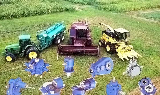
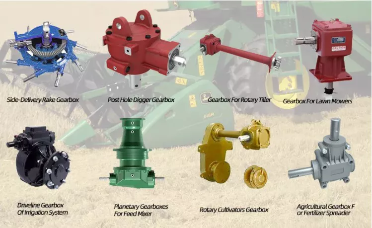
China high quality Speed Increaser Agricultural Gearbox for Agriculture Machinery with Great qualityProduct Description
Product Description
Company Profile In 2571, HangZhou CZPT Machinery Co.,ltd was established by Ms. Iris and her 2 partners(Mr. Tian and Mr. Yang) in HangZhou city(ZHangZhoug province, China), all 3 Founders are engineers who have more than averaged 30 years of experience. Then because the requirements of business expansion, in 2014, it moved to the current Xihu (West Lake) Dis. Industrial Zone (HangZhou city, ZHangZhoug province, China). Through our CZPT brand ND, CZPT Machinery delivers agricultural solutions to agriculture machinery manufacturer and distributors CZPT through a full line of spiral bevel gearboxes, straight bevel gearboxes, spur gearboxes, drive shafts, sheet metal, hydraulic cylinder, motors, tyre, worm gearboxes, worm operators etc. Products can be customized as request. We, CZPT machinery established a complete quality management system and sales service network to provide clients with high-quality products and satisfactory service. Our products are sold in 40 provinces and municipalities in China and 36 countries and regions in the world, our main market is the European market. Certifications
Our Factory Sample Room Why choose us? 1) Customization: With a strong R&D team, and we can develop products as required. It only takes up to 7 days for us to design a set of drawings. The production time for new products is usually 50 days or less. 2) Quality: We have our own complete inspection and testing equipment, which can ensure the quality of the products. 3) Capacity: Our annual production capacity is over 500,000 sets, also, we also accept small quantity orders, to meet the needs of different customer’s purchase quantities. 4) Service: We focus on offering high-quality products. Our products are in line with international standards and are mainly exported to Europe, Australia, and other countries and regions. 5) Shipment: We are close to HangZhou and ZheJiang ports, to provide the fastest shipping service. Packaging & Shipping
FAQ Q: Are you a trading company or manufacturer? Q: Do you provide samples? is it free or extra? Q: How long is your delivery time? What is your terms of payment? Q: What is the exact MOQ or price for your product? If you have another question, please feel free to contact us.
The Different Types of GearboxesThere are many different types of gearboxes. Some brands have more than one type. In this article, we’ll discuss the planetary gearbox, the worm reduction gearbox, the shaft mounted gearbox, and the one speed gearbox. This article will also help you determine which type of gearbox is best for your vehicle. And don’t worry if you don’t know the terminology yet. We’ll explain each type in detail so that you know what you’re getting yourself into. Planetary gearboxPlanetary gears have many advantages. The multiple gears in a planetary gearbox mesh simultaneously during operation. As such, they provide high efficiency and transmit high transmittable torque. These gears are widely used in various industries and are resistant to high shock loads and demanding conditions. CZPT is one of the companies that offer planetary gearboxes. Its products do not require special tools for assembly, and its scalable design minimizes safety stock. Worm reduction gearboxThe global worm reduction gearbox market report compiles key insights from the industry to help you improve your business strategy. This report will help you create a comprehensive business document that will enhance your company’s competitive edge. To obtain this report, visit our website now! Read our latest report to find out what you can expect from the global worm reduction gearbox market. Alternatively, request a sample copy for more details. Here is a sneak peek of the report: Shaft-mounted gearboxShaft-mounted gearboxes are designed for a variety of mining and quarry applications. Their high reliability and low maintenance make them an excellent choice in these types of applications. Shaft-mounted gearboxes also feature an optional backstop device that prevents the unit from rotating in one direction. This makes them an excellent choice for applications where alignment accuracy is an issue. Here are some of the benefits of using a shaft-mounted gearbox: 1 speed gearboxCZPT Group Components produces one speed gearboxes. These transmissions are produced in the CZPT Group’s Kassel plant. They are compact and robust, and are designed for easy integration. The Bosch Rexroth GD1 one-speed gearbox is easy to install horizontally or vertically. The Plug and Drive system integrates the gearbox with the existing cooling system. There are many other benefits to this gearbox.
China Hot Sale Mixer Gear Box for Concrete Machinery gearbox definitionProduct Description
We, Xihu (West Lake) Dis.ng group can give total established of concrete pump spare components: dress in pla
Connected Concrete Spare Areas Our Factory Business Certificates Firm Profile HangZhou Xihu (West Lake) Dis.ng Substance Co., Ltd, started business since 1991, and was formally proven as a registered organization in 2002, with 5.3million RMB registered cash. Just before 2015, Xihu (West Lake) Dis.ng centered on the domestic industry, and is a qualified provider of Jianglu group and CZPT in the armed forces and mechanical items. In 2015, Xihu (West Lake) Dis.ng set up the intercontinental marketing division, specializing in exporting concrete building machinery, mining Roadheaders, and the related spare parts and accessories. With manufacturing bases in HangZhou, HangZhou and HangZhou metropolitan areas. Xihu (West Lake) Dis.ng owns branches “Cahi “in Kiev Ukraine, and “Speedlane Trade Constrained” abroad business. Primarily export to Pakistan, Ukraine, Russia, and other EU international locations and Southeast Asian international locations below our possess brands “Speedlane” and ” XIHU (WEST LAKE) DIS.NG”. Xihu (West Lake) Dis.ng has acquired the CE certificate, and Ukraine’s Coal Mining Protection certificate and permission. Cooperated with Ukraine largest strength organization, DTEK team, the planet best five hundred, and proven a long expression and friendly partnership.
###
###
###
###
What Is a Gearbox?A gearbox is the mechanical system of an automobile that allows a vehicle to change gear smoothly. This arrangement of gears is highly complex, which helps to provide a smooth gear change. In this article, we will explore some of the different types of gearboxes, including the Epicyclic gearbox, the Coaxial helical gearbox, and the Extruder helical gearing. These are three of the most common types of gearboxes used in automobiles. GearboxesGearboxes help drivers choose the appropriate gear for the conditions. A lower gear produces the least speed, while a higher gear gives the maximum torque. The number of gears used in a gearbox varies to meet different demands on the road and load. Short gearing provides maximum torque, while tall gearing offers higher top speeds. These features combine to improve the driveability of a vehicle. But what is a gearbox? Coaxial helical gearboxThe R series rigid tooth flank helical gearbox features high versatility and good combination. They have a wide range of motor power and allow for fine classification of transmission ratios. The R series gearbox has several advantages, including high efficiency, long service life, and low vibration. This series of gearbox can be combined with a wide range of reducers and variators. Its size and high performance makes it an ideal choice for applications that require maximum torque and load transfer. Epicyclic gearboxAn epicyclic gearbox is a type of automatic gearbox used to drive cars. Its primary advantage is its compact design, and it is more reliable and efficient than manual gearboxes. It is comprised of a sun gear and two planetary gears, encased in a ring gear called the Annulus. This system is useful for drivers who need to shift gears frequently, as they will become tired if the gears are suddenly changed. Extruder helical gearingThe helix in an extruder helical gearing is fixed at an angle, enabling more interaction with the shaft in the same direction as it moves. As a result, the shaft and the bearing are in constant contact for a long period of time. Typically, extruder helical gearing is used in applications where there is low excitement, such as steel, rolling mills, conveyors, and the oil industry. The bevel gear train also plays a role in these applications. 1 speed gearboxCZPT Group Components produces the one speed gearbox. It has the potential to make cars more efficient and environmentally friendly. The gear ratio of a car’s drivetrain is crucial for reaching maximum power and speed. Typically, a one-speed gearbox delivers a maximum of 200 hp. But the speed at which a car can reach this power must be high to get the full benefit from the electric motor. So, how can a one-speed gearbox improve the speed and torque of a car?
| |||||||||||||||||||||||||||||||||||||||||||||||||||||||||||||||||||||||||||||||||||||||||||||||||||||||||||||||||||||||||||||||||||||||||||||||||||||||||||||||||||||||||||||||||||||||||||||||||||||||||||||||||||||||||||||||||||||||||||||||||||||||||||||||||||||||||||||||||||||||||||||||||||||||||||||||||||||||||||||||||||||||||||||||||||||||||||||||||||||||||||||||||||||||||||||||||||||||||||||||||||||||||||||||

